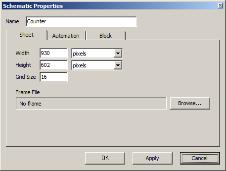
Schematic properties apply to the currently active schematic, and will be saved in the schematic file. No other schematic will be affected. To set default properties for new schematics, use the Options dialog.
Width. The width of the schematic, given in the unit specified in the drop-down list immediately to the right of the number.
Height. The height of the schematic, given in the unit specified in the drop-down list immediately to the right of the number.
Grid Size. The length in pixels of the sides of the squares that constitute the grid.
Frame File. The full path to the file containing the frame definition, or No frame if no frame has been added. A new frame can be added to the schematic by clicking the Browse... button and selecting a frame file. A frame is an add-on of graphics to schematics, typically used to enhance the appearance of a printed schematic. However, there is no way to create a frame file in the current version of RTflow, so this should be seen as a future feature.
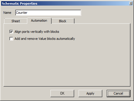
Align ports vertically with blocks. When checked, all port blocks in the schematic are vertically aligned with the port instance it is connected to. As a result, it is impossible to move a port block vertically by dragging it with the mouse, unless the block instance it is connected to is also moved.
Add and remove Value blocks automatically. When checked, a Value block is always inserted automatically as soon as there is an unconnected input port instance in the schematic, and the new Value block is connected to that port instance. Moreover, unconnected Value blocks are always deleted. As a result, you can not add or remove Value blocks manually as with other blocks - this happens automatically under the mentioned conditions.
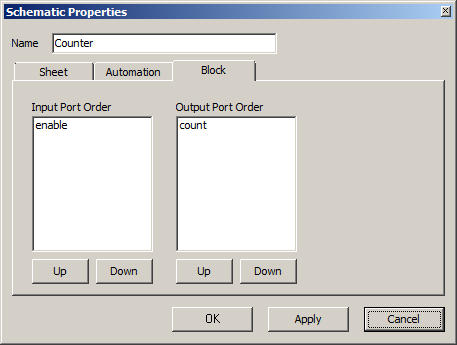
Input port order. The order in which the input ports will appear on the left side of the block that this schematic defines. Select a port in the list and press the Up or Down buttons below the list to move the port up and down. After changing the order and clicking OK or Apply, the schematic must also be compiled to apply the changes to the block.
Output port order. The order in which the output ports will appear on the right side of the block that this schematic defines. Select a port in the list and press the Up or Down buttons below the list to move the port up and down. After changing the order and clicking OK or Apply, the schematic must also be compiled to apply the changes to the block.