The Simulator (Tutorial)
This section explains how to verify the counter using the built-in simulator.
Set up the simulator
Before simulation can start, the schematic needs to be compiled. Moreover, it is necessary to set up a few simulation parameters. In particular, since the project can contain many schematics, it is necessary to specify which schematic to simulate.
- Start simulation by choosing Project:Simulate, by clicking the Simulate toolbar button or by pressing F9.
- If the schematic has not yet been compiled, it must now be given a name. Enter Counter and press Enter.
- The schematic is now automatically compiled. If there are any errors, they will be printed in the message pane in the bottom of the window. Fix the errors and start simulation again. See the Compiler Errors chapter for documentation of error messages.
- When asked to set up simulation, choose OK.
- The Simulation page of the Project Settings dialog appears. In the Top-Level Node drop-down list, choose Counter as the schematic to simulate. Then click OK. (The Sample Time setting is irrelevant for a model that doesn't contain time-dependent blocks like integration, so it can be left at its default setting.)
Simulate with the simulator view
When the simulation has started, the simulator view appears under a new tab in the same area as the schematic editor. The simulator view is divided into two main areas: the signal area to the left shows the names and the current values of the signals, and the graph area to the right shows the simulated data graphically. As the simulation progresses, the graphs will be plotted towards the right. By default, the graphs are shown individually in rows aligned with their names, but the graphs can also be shown in full size in the graph area by clicking the Joint View toolbar button.
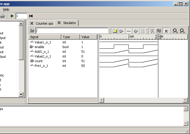
- Execute one cycle by clicking the Simulate toolbar button or by pressing F9. No values will change because enable is 0, but a pixel is added to each graph in the graph area.
- Press and hold F9 to execute more cycles and see the graph being plotted.
- Enter 10 in the simulation time box to the right of the Simulate toolbar button and then click the button or press F9 to execute ten cycles at once.
Force a signal
Individual signal values can be forced to any value during the simulation by clicking in the Value or the Force column. For boolean signals, the value will switch between 0 and 1 when clicked, while for other types, a box appears where a new value can be entered. Forcing is removed by right-clicking the value and choosing Unforce in the context menu that appears.
- Click the 0 in the Value column for the enable signal to force this signal to 1. Notice that count also immediately switches to 1, since the value of count is dependent on the value of enable in the same cycle.
- Click the Simulate toolbar button or press F9 a few times to see the value of count increase.
- Right-click the 1 and click Unforce to remove the forcing.
Move the cursor to examine simulation results
The cursor is a vertical line that is always present in the graph area, by default at the right end of the graphs. However, the cursor can be moved by clicking in the graph area or by pressing Ctrl-Left arrow or Ctrl-Right arrow. The values shown in the signal area always reflect the values at the cursor's position.
- Click in the middle of the graph. The cursor will move to this position, and the signal area will show the values at this position.
- Press Ctrl-Left arrow and Ctrl-Right arrow to move the cursor one cycle to the left and to the right, respectively.
View values in the schematic
Simulated signal values can also be viewed in the schematic right by the corresponding connections. As with the signal area, the schematics reflect the values of the cursor, even if the cursor is not explicitly visible.
- Click the Counter.sps tab to show the schematic.
- Click the Show Values toolbar button. The current signal values are now shown above the connections.
- Click the Simulate toolbar button or press F9 to see the values change.
- Press Ctrl-Left arrow and Ctrl-Right arrow to step backwards and forwards in the simulation result.
Set up a testbench
A common way to perform simulation is to set up a testbench where input data is fed automatically into the model. In RTflow, this can be done by using the model as a block in another schematic and connecting this block to a signal generator.
- Create another schematic.
- Find the Counter block in the User folder at the bottom of the blocks tree. This block was automatically added when the Counter schematic was compiled in the beginning of this section.
- Drag the Counter block into the new schematic.
- Find the block Clock under Standard and Generator in the blocks tree, and drag it into the same schematic. This block produces a boolean signal that switches between 0 and 1 at a given period.
- Connect the o port of Clock1 to the enable port of Counter1.
- Add a Value block with value 100 and connect it to the t port of Clock1. This sets the period of Clock1 to 100 cycles.
The above procedure exemplifies how models can be structured into a hierarchy of schematics. A typical model has a top-level schematic containing the model's inputs and outputs and a number of connected user-defined blocks. These blocks have been defined in schematics that may again contain other user-defined blocks. The definition of a block can be opened by double-clicking it, and one can return to the parent schematic by clicking the Pop Context toolbar button in the schematic editor.
Simulate with the testbench
Since the simulator is now set up to simulate the Counter schematic, it is necessary to change this setting to simulate the Testbench schematic and restart the simulator.
- Compile the new schematic by choosing Project:Compile or by pressing F11. Give it the name Testbench.
- Open the project settings dialog by choosing Project:Settings....
- Change the top-level node to Testbench and click OK.
- Restart the simulator by choosing Project:Reset Simulator or by clicking the Reset Simulator toolbar button. The simulator view appears, showing the signals of the testbench schematic.
- Double-click the Counter1 folder to view the signals of the counter model.
- Press and hold F9 to simulate at least 100 cycles to see that enable switches automatically every 50th cycle.